 Hyundai Accent: Removal and Installation
Hyundai Accent RB (2010-2018) Service Manual / Engine Electrical System / Charging System / Alternator. Repair procedures / Removal and Installation
| 1. |
Disconnect the battery negative terminal first, then
the positive terminal.
|
| 2. |
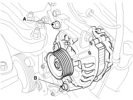
Loosen the mounting bolts (A,B)
|
| 3. |
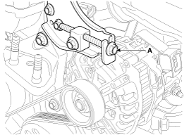
Turn the adjusting bolt(B) clockwise in loose tension.
|
| 4. |
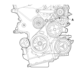
Remove the drive belt (A).
|
| 5. |
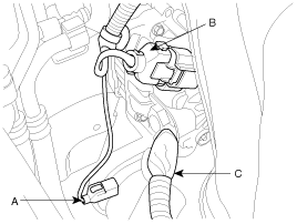
Disconnect the air compressor connector(A) and the
alternator connector (B), and remove the cable (C) from alternator "B"
terminal.
|
| 6. |
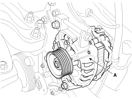
Remove the alternator(A).
|
| 7. |
Installation is the reverse order of removal.
|
| 8. |
Adjust the alternator belt tension after installation.
|
 Disassembly
1.
Remove the rear cover (A).
2.
Loosen the mounting bolts(A) and disconnect the brush
holder assembly(B).
...
See also:
Replacement
1.
Remove the rear wheel & tire.
Tightening torque :
88.3 ~ 107.9N.m(9.0 ~ 11.0kgf.m, 65.1 ~ 79.6lb-ft)
...
Turn signals and lane change signals
The ignition switch must be on for the turn signals to function. To turn on the
turn signals, move the lever up or down (A). Green arrow indicators on the instrument
panel indicate which turn si ...
Inspection
Remove the overhead console lamp assembly then check for continuity between
terminals. If the continuity is not as specified, replace the map lamp switch.
...
Hyundai Accent Manuals
В© 2011-2026 Copyright www.hamanual.com

