 Hyundai Accent: Repair procedures
Hyundai Accent RB (2010-2018) Service Manual / Body Electrical System / Keyless Entry / Repair procedures
Inspection
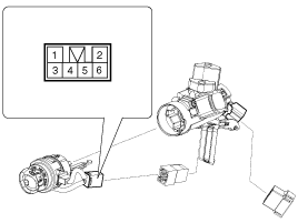
Front Door Lock Actuator
| 1. |
Remove the front door trim.
(Refer to the Body group - Front door)
|
| 2. |
Remove the front door latch.
(Refer to the Body group - Front door).
|
| 3. |
Disconnect the connectors from the actuator.
|
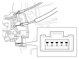
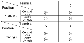
| 4. |
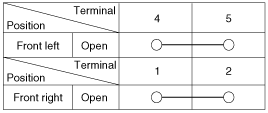
Check actuator operation by connecting power and ground according
to the table. To prevent damage to the actuator, apply battery voltage
only momentarily.
|
Rear Door Lock Actuator
| 1. |
Remove the rear door trim.
(Refer to the Body group - Rear door)
|
| 2. |
Remove the rear door latch.
(Refer to the Body group - Rear door)
|
| 3. |
Disconnect the connectors from the actuator.
|
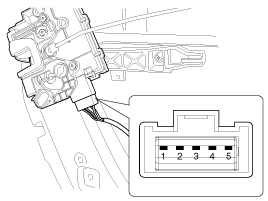
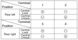
| 4. |
Check actuator operation by connecting power and ground according
to the table. To prevent damage to the actuator, apply battery voltage
only momentarily.
|
Front Door Lock Switch
| 1. |
Remove the front door trim.
(Refer to the Body group - Front door)
|
| 2. |
Remove the front door latch.
(Refer to the Body group - Front door).
|
| 3. |
Disconnect the connectors from the actuator.
|
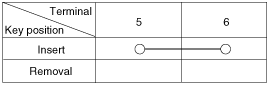
| 4. |
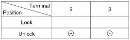
Check for continuity between the terminals in each switch position
when inserting the key into the door according to the table.
|
Rear Door Lock Switch
| 1. |
Remove the rear door trim.
(Refer to the Body group - Rear door)
|
| 2. |
Remove the rear door latch.
(Refer to the Body group - Rear door)
|
| 3. |
Disconnect the connectors from the actuator.
|
| 4. |
Check for continuity between the terminals in each switch position
according to the table.
|
Trunk lid release actuator
| 1. |
Disconnect the negative battery terminal.
|
| 2. |
Remove the rear trunk lid trim, and then remove the trunk lid
switch from the actuator.
|
| 3. |
Check for continuity between the terminals in each switch position
according to the table.
|
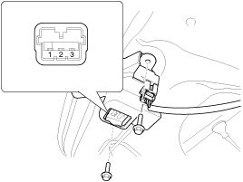
Door switch
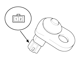
Remove the door switch and check for continuity between the terminals.
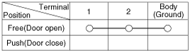
Door warning switch
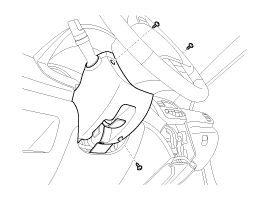
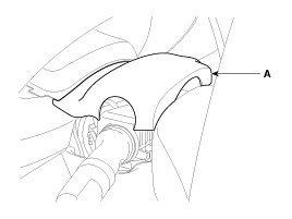
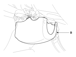
| 1. |
Remove the steering column upper (A) and lower (B) shrouds after
removing 3 screws.
|
| 2. |
Disconnect the connector (6p) from the door warning switch.
|
| 3. |
Check for continuity between the terminals in each position according
to the table.
|
 Function
Keyless Entry Function
DOOR LOCK / UNLOCK are performed with remote controller.
1.
Keyless entry function is performed in a state that key in switch
is eliminated ...
 Transmitter. Specifications
Specifications
Item
Specification
Rated voltage
DC 3V
Service voltage range
DC 2.7V ~ 3.5V
Temperatu ...
See also:
Installation
1.
Remove the ignition key from the vehicle.
2.
Disconnect the battery negative cable from battery and wait for
at least three minutes befo ...
Head Lamps. Components and Components
Location
Component
1. Head lamp assembly lens & housing
2. Head lamp (High/Low)
3. Dust cap
4. Turn signal lamp
...
Installation
Be sure to install the harness wires not to be pinched or interfered
with other parts.
...
Hyundai Accent Manuals

© 2011-2026 Copyright www.hamanual.com