 Hyundai Accent: Installation
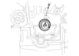
| 1. |
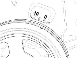
Dowel pin of crankshaft should be positioned at 3°
in relation to vertical center line.
|
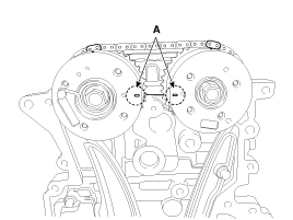
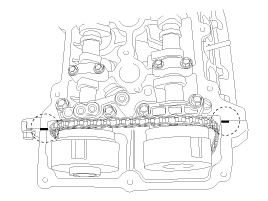
| 2. |
Align the TDC marks (A) of the CVVT sprockets with
the upper surface of the cylinder head to make No.1 cylinder be positioned
at TDC.
|
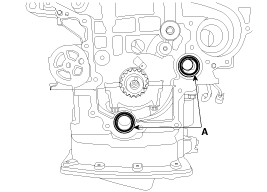
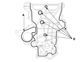
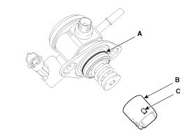
| 3. |
Install the new O-rings (A).
|
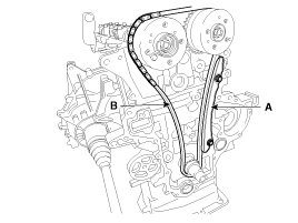
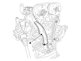
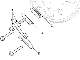
| 4. |
Install the timing chain guide (A) and the timing
chain (B).
|
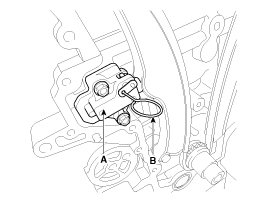
| 5. |
Install the chain tensioner arm (A).
|
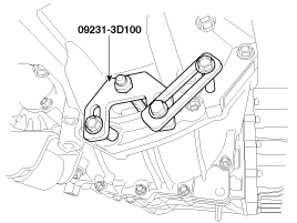
| 6. |
Install the hydraulic tensioner (A) and remove the
pin (B).
|
| 7. |
Install the timing chain cover.
|
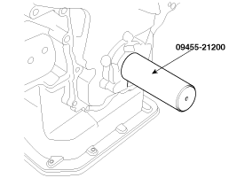
| 8. |
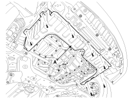
Using the SST(09455-21200), reassemble the timing
chain cover oil seal.
|
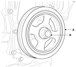
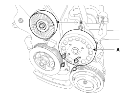
| 9. |
Install the crankshaft pulley (A).
|
| 10. |
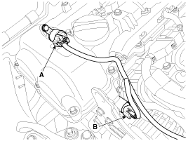
Install the water pump (A) with a gasket.
|
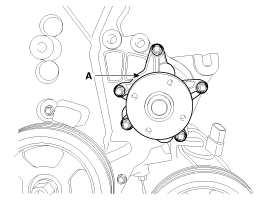
| 11. |
Install the water pump pulley (A) and the drive belt
idler (B).
|
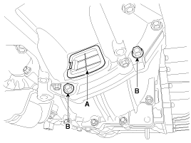
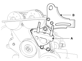
| 12. |
Install the engine support bracket (A).
|
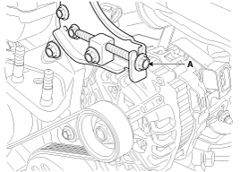
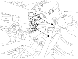
| 13. |
Install the alternator bracket (B).
|
| 14. |
Install the engine mounting support bracket (B) and
connect the ground cable (A)
|
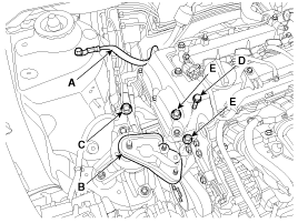
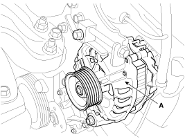
| 15. |
Install the alternator (A).
|
| 16. |
Install the drive belt (A).
|

| 17. |
Adjust tension by tightening the alternator tension
adjust bolt (A).(Refer to Charging system in EE Group).
|
| 18. |
Before installing the cylinder head cover, remove
oil, dust or hardened sealant from the timing chain cover and the cylinder
head upper surface.
|
| 19. |
After applying the liquid gasket, Hyundai Gray RTV
or THREE BOND 1217H or LOCTITE 5900H on the cylinder head cover, reassemble
the cover within five minutes.
|
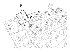
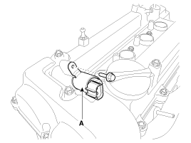
| 20. |
Install the OCV (Oil Control Valve) adapter (A).
|
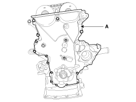
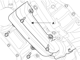
| 21. |
Install the cylinder head cover (A) with a new gasket
(B).
|
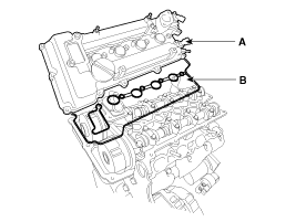
| 22. |
Tighten the cylinder head cover bolts with the order
and steps.
|

| 23. |
Install the exhaust OCV (Oil Control Valve) (A).
|
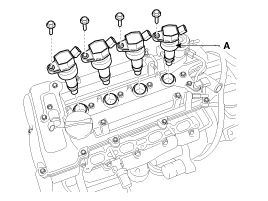
| 24. |
Install the ignition coils (A).
|
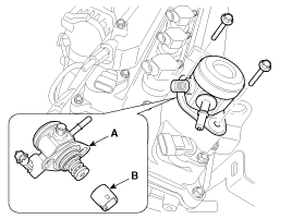
| 25. |
Install the high pressure fuel pump (A) and the roller
tappet (B). (Refer to FL group)
|
| 26. |
Install the high pressure pipe (A). (Refer to FL
group)
|

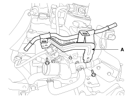
| 27. |
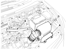
Install the vacuum pipe assembly (A).
|
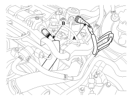
| 28. |
Connect the fuel hose (A) and the PCV (Positive crankcase
ventilation) hose (B).
|
| 29. |
Connect the FPCV (Fuel pressure control valve) connector
(A), the intake CMPS (Camshaft position sensor) connector (B), the exhaust
CMPS (Camshaft position sensor) connector (C).
|
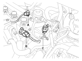
| 30. |
Connect the oxygen sensor connectors (A), the condenser
connector (B).
|
| 31. |
Connect the ignition coil connectors (A), the injector
extension connector (B), the VIS (Variable intake system) connector
(C) and the PCSV (Purge control solenoid valve) connector (D).
|
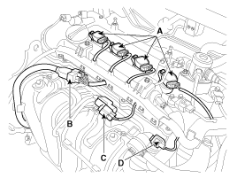
| 32. |
Connect the intake OCV (Oil control valve) connector
(A) and the exhaust OCV (Oil control valve) connector (B).
|
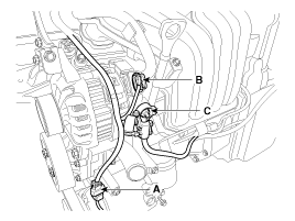
| 33. |
Connect the A/C compressor switch connector (A),
the alternator connector (B) and the cable from the alternator “B” terminal
(C).
|
| 34. |
Install the under covers (A).
|
| 35. |
Install the RH front wheel.
|
| 36. |
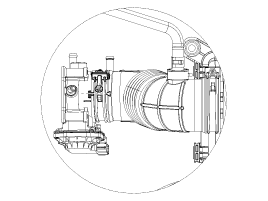
Install the air cleaner assembly.
|
| 37. |
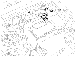
Connect the battery negative terminal (A).
|
| 38. |
Install the engine cover.
|
 Inspection
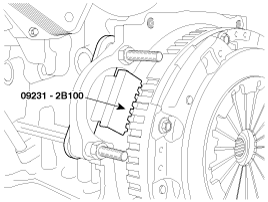
Sprockets, Hydraulic
Tensioner, Chain Guide, Tensioner Arm
1.
Check the CVVT sprocket, crankshaft sprocket teeth
for abnormal wear, cracks or damage. Repla ...

See also:
Starting the engine
WARNING
Always wear appropriate shoes when operating your vehicle. Unsuitable shoes
(high heels, slippers, ski boots, etc.) may interfere with your ability to use the
brake, accelerator pedal, a ...
Highway driving
Tires
Adjust the tire inflation pressures to specification. Low tire inflation pressures
will result in overheating and possible failure of the tires.
Avoid using worn or damaged tires which may ...
TCM Terminal Input/ Output Signal
Connector [CHG-AA]
Pin
Description
Condition
Input/output value
Type
Level
22
Overdrive clutch c ...
Hyundai Accent Manuals
