 Hyundai Accent: Disassembly
| 1. |
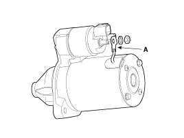
Disconnect the M-terminal (A) on the magnet switchassembly.
|
| 2. |
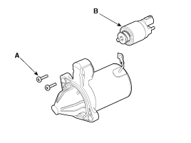
After loosening the 2 screws (A), detach the magnetswitch
assembly (B).
|
| 3. |
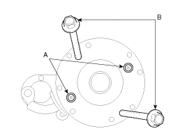
Loosen the through bolts (A).
|
| 4. |
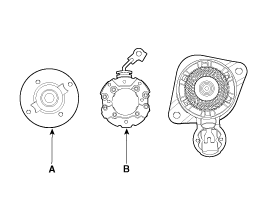
Remove the rear bracket (A) and brush holderassembly
(B).
|
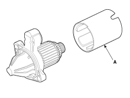
| 5. |
Remove the yoke (A).
|
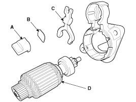
| 6. |
Remove the packing (A), lever plate (B), lever (C)
and the armature (D).
|
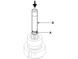
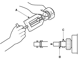
| 7. |
Press the stopper (A) using a socket (B).
|
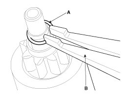
| 8. |
After removing the stop ring (A) using stopper pliers(B).
|
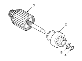
| 9. |
Remove the stop ring (B), stopper (A), overrunningclutch
(C) and armature (D).
|
| 10. |
Reassembly is the reverse of disassembly.
|
 Removal and Installation
1.
Disconnect the battery negative terminal.
Tightening torque
(-) terminal :
4.0 ~ 6.0N.m (0.4 ~ 0.6kgf.m, 3.0 ~ 4.4l ...
 Inspection
Armature
1.
Remove the starter.
2.
Disassemble the starter as shown at the beginning
of this procedure.
3 ...
See also:
Removal
Pressure Side Impact Sensor
•
Removal of the airbag must be performed according to the ...
Headlamp delay
If you turn the ignition switch to the ACC or OFF position with the headlights
ON, the headlights remain on for about 20 minutes. However, if the driver’s door
is opened and closed, the headligh ...
Carry emergency equipment
Depending on the severity of the weather where you drive your car, you should
carry appropriate emergency equipment. Some of the items you may want to carry include
tire chains, tow straps or chai ...
Hyundai Accent Manuals
© 2011-2026 Copyright www.hamanual.com

