|
1. |
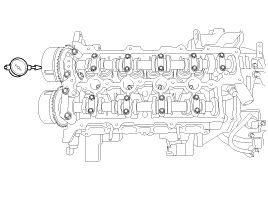
Inspect the Continuous variable valve timing (CVVT)
assembly.
|
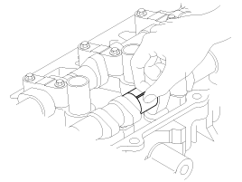
(1) |
Fix the Continuous variable valve timing
(CVVT ) with its camshaft in a vice.
|
|
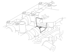
(2) |
Check that the CVVT assembly will not turn.
If it is not turned, it is in normal condition.
|
|
(3) |
Apply vinyl tape to all the parts except
the one hole.
|
|
(4) |
Using an air gun, apply the pressure, 147.10kpa
(1.5kg/cm², 21.33psi) in the hole. This makes the lock pin in
maximum retarded state released.
|
• |
Wrap around it with a shop
rag, because the oil can splash out..
|
|
• |
After releasing the pin,
you can turn the CVVT assembly for advance by
hand.
|
|
• |
If there was too much air
leakage, the pin can not be released.
|
|
|
|
(5) |
Under the condition of 3), turn the CVVT
assembly to the advance angle side with your hand.
Depending on the air pressure, the CVVT assembly
will turn to the advance side.
Also, if the air pressure that wasapplied
was insufficient because of the air leakage from the port, the
lock pin may not release properly.
|
|
(6) |
Except the position where the lock pin meets
at the maximum delay angle, let the CVVT assembly turn back
and forth and check the movable range and that there is no interference.
Standard
: Movable smoothly in the
range about 25°
|
|
|
(7) |
Turn the CVVT assembly with your hand counterclockwise
and lock it at the maximum delay angle position.
|
|
 Hyundai Accent: Inspection
 Disassembly
 Reassembly