 Hyundai Accent: Power Window Switch. Repair procedures
Inspection
| 1. |
Disconnect the negative (-) battery terminal.
|
| 2. |
Remove the front door trim panel.
(Refer to the BD group - "Front door")
|
| 3. |
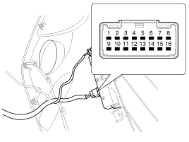
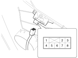
Disconnect the connector from the switch.
|
| 4. |
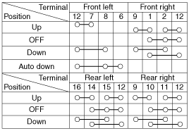
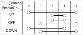
Check for continuity between the terminals in each switch position
according to the table. If the continuity condition is not normal, replace
the switch.
[Auto Down]
|
| 1. |
Disconnect the negative (-) battery terminal.
|
| 2. |
Remove the front door trim panel.
(Refer to the BD group - "Front door")
|
| 3. |
Disconnect the connector from the switch.
|
| 4. |
Check for continuity between the terminals in each switch position
according to the table. If the continuity condition is not normal, replace
the switch.
|
| 1. |
Disconnect the negative (-) battery terminal.
|
| 2. |
Remove the rear door trim panel.
(Refer to the BD group - "Rear door")
|
| 3. |
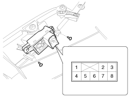
Disconnect the 8P connector from the switch.
|
| 4. |
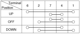
Check for continuity between the terminals in each switch position
according to the table. If the continuity condition is not normal, replace
the switch.
|
See also:
Identification Number Description. Vehicle Identification Number
1.
World Manufacturer Identifier (WMI)
- KMF : Commercial vehicle (Van)
- KMH : Passenger vehicle or MPV(Multipurpose Passenger
Vehicle)/SUV(Sports Util ...
Steering Angle Sensor. Description and Operation
Description
The steering angle speed sensor detects the angle of the steering wheel
in order to which direction a user chooses.The sensor is detached on the MPS(Mutil-Function
Switch) under ...
Components and Components
Location
Components
1. HECU module
2. Front wheel speed sensor
3. Rear wheel speed sensor
4. Yaw rate & Lateral G sensor
5. Steering angle sensor
6. ABS Warning l ...

