 Hyundai Accent: Sub Frame. Repair procedures
Hyundai Accent RB (2010-2018) Service Manual / Suspension System / Front Suspension System / Sub Frame. Repair procedures
Replacement
| 1. |
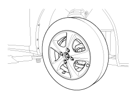
Remove the front wheel & tire.
|
| 2. |
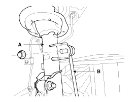
Disconnect the stabilizer link (B) with the front strut assembly
(A) after loosening the nut.
|
| 3. |
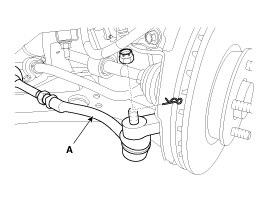
Loosen the nut and then remove the tie-rod end (A) with the front
axle (B).
|
| 4. |
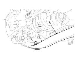
Loosen the nut and then remove the lower arm (A).
|
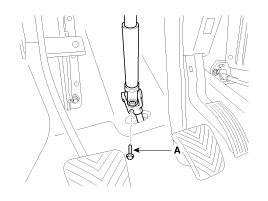
| 5. |
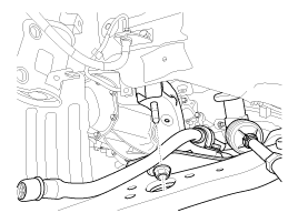
Loosen the bolt (A) and then disconnect the universal joint assembly
from the pinion of the steering gear box.
|
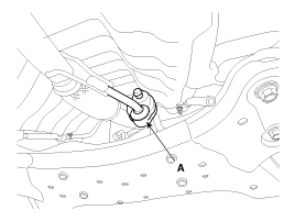
| 6. |
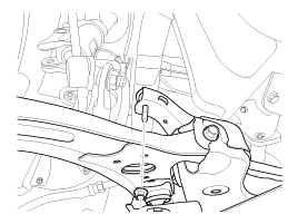
Remove the rubber hanger (A).
|
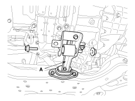
| 7. |
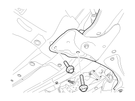
Remove the cross member from the body by loosening the roll rod
(A) mounting bolts and nuts.
|
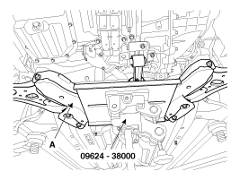
| 8. |
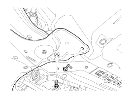
Loosen the bolts & nuts and then remove the front sub frame (A).
|
| 9. |
Installation is the reverse of removal.
|
 Inspection
1.
Check the bushing for wear and deterioration.
2.
Check the front stabilizer bar for deformation.
3.
Check th ...
See also:
Installation
When replacing the ECM, the vehicle equipped with
the immobilizer must be performed procedure as below.
[In the ...
Interior C ( 4Door )
Front pillar trim mounting hole (Ø8.5)
Front pillar trim mounting hole (Ø8)
Cowl cross ...
Tire chains
Tire chains, if necessary, should be installed on the front wheels.
Be sure that the chains are installed in accordance with the manufacturer's instructions.
To minimize tire and chain wear, do ...
Hyundai Accent Manuals
© 2011-2026 Copyright www.hamanual.com

