 Hyundai Accent: Sunroof Motor. Repair procedures
Hyundai Accent RB (2010-2018) Service Manual / Body Electrical System / Sun Roof / Sunroof Motor. Repair procedures
Replacement
| 1. |
Disconnect the negative (-) battery terminal.
|
| 2. |
Remove the roof trim. (Refer to the BD group - " Roof trim")
|
| 3. |
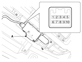
Disconnect the connector and remove the sunroof motor (A) with
loosening 2 screws.
|
| 4. |
Ground the terminals as below table, and check that the sunroof
unit operates as below table.
|
| 5. |
Make these input tests at the connector.
If any test indicates a problem, find and correct the cause, then
recheck the system.
If all the input tests prove OK, the sunroof motor must be faulty;
replace it.
|
Resetting The Sunroof
Whenever the vehicle battery is disconnected or discharged, or you use
the emergency handle to operate the sunroof, you have to reset your sunroof
system as follows :
| 1. |
Turn the ignition key to the ON position.
|
| 2. |
According to the position of the sunroof, do as follows.
|
| 3. |
Release the TILT button.
|
| 4. |
Press and hold the TILT button once again until the sunroof has
returned to the original position of TILT after it is raised a little
higher than the maximum TILT position.
When this is complete, the sunroof system is reset.
|
Protecting Motor From Overheating
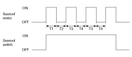
In order to protect the sunroof motor from overheating from continuous
motor operation, the sunroof ECU controls the Run-time and Cool-time of the
motor as follows:
| 1. |
The Sunroof ECU detects the Run- time of motor
|
| 2. |
Motor can be operated continuously for the 1st run-time(120 ±
10sec.).
|
| 3. |
The continuous operation of motor stops after the 1st Run-time(120
± 10sec.).
|
| 4. |
Then Motor is not operated for the 1st Cool-time(18 ± 2sec.).
|
| 5. |
Motor is operated for the 2nd Run-time(10 ± 2sec.) at the continued
motor operation after 1st Cool-time(18 ± 2sec.)
|
| 6. |
The continuous operation of motor stops operating after the 2nd
Run-time(10 ± 2sec.)
|
| 7. |
Motor is not operated for the 2nd Cool-time(18 ± 2sec.).
|
| 8. |
Motor repeats the 2nd run-time and 2nd cool-time at the continued
motor operation.
T1 : 120 ± 10 sec., T2 : 18 ± 2 sec.,
T3 : 10 ± 2 sec., T4 : 18 ± 2 sec.
|
 Sunroof Switch. Repair procedures
Inspection
1.
Disconnect the negative (-) battery terminal.
2.
Open the sunglass case cover from the overhead console then remove
the 2 sc ...
See also:
Clothes hanger
To use the hanger, pull down the upper portion of hanger.
CAUTION
Do not hang heavy clothes, because it may damage the hook. ...
Inspection
Armature
1.
Remove the starter.
2.
Disassemble the starter as shown at the beginning
of this procedure.
3 ...
Reset items
Items should be reset after the battery has been discharged or the battery has
been disconnected.
Auto up/down window (See section 4)
Sunroof (See section 4)
Trip computer (See section 4)
...
Hyundai Accent Manuals
- Hyundai Accent 2017-2022 Service Manual
- Hyundai Accent 2010-2025 Owners Manual
- Hyundai Accent 2010-2025 Service Manual
© 2011-2025 Copyright www.hamanual.com


