
 Hyundai Accent: Tightening Torque Table Of Standard Parts
Hyundai Accent RB (2010-2018) Service Manual / General Information / Tightening Torque Table Of Standard Parts
|
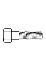
Bolt nominal diameter (mm) |
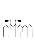
Pitch (mm) |
Torque Nm (kg.cm, lb.ft) |
|
|
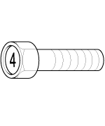
Head Mark 4 |
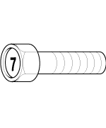
Head Mark 7 |
||
|
|
|
|
|
|
M5 |
0.8 |
3 ~ 4 (30 ~ 40, 2.2 ~ 2.9) |
5 ~ 6 (50 ~ 60, 3.6 ~ 4.3) |
|
M6 |
1.0 |
5 ~ 6 (50 ~ 50, 3.6 ~ 4.3) |
9 ~ 11 (90 ~ 110, 6.5 ~ 8.0) |
|
M8 |
1.25 |
12 ~ 15 (120 ~ 150, 9 ~ 11) |
20 ~ 25 (200 ~ 250, 14.5 ~ 18.0 ) |
|
M10 |
1.25 |
25 ~ 30 (250 ~ 300, 18 ~ 22) |
30 ~ 50 (300 ~ 500, 22 ~ 36) |
|
M12 |
1.25 |
35 ~ 45 (350 ~ 450, 25 ~ 33) |
60 ~ 80 (600 ~ 800, 43 ~ 58) |
|
M14 |
1.5 |
75 ~ 85 (750 ~ 850, 54 ~ 61) |
120 ~ 140 (1,200 ~ 1,400, 85 ~ 100) |
|
M16 |
1.5 |
110 ~ 130 (1,100 ~ 1,300, 80 ~ 94) |
180 ~ 210 (1,800 ~ 2,100, 130 ~ 150) |
|
M18 |
1.5 |
160 ~ 180 (1,600 ~ 1,800, 116 ~ 130) |
260 ~ 300 (2,600 ~ 3,000, 190 ~ 215) |
|
M20 |
1.5 |
220 ~ 250 (2,200 ~ 2,500, 160 ~ 180) |
360 ~ 420 (3,600 ~ 4,200, 260 ~ 300) |
|
M22 |
1.5 |
290 ~ 330 (2,900 ~ 3,300, 210 ~ 240) |
480 ~ 550 (4,800 ~ 5,500, 350 ~ 400) |
|
M24 |
1.5 |
360 ~ 420 (3,600 ~ 4,200, 260 ~ 300) |
610 ~ 700 (6,100 ~ 7,000, 440 ~ 505) |
|

 Emergency Towing
There are three popular methods of towing a vehicle :
-
The operator loads the vehicle on the back of truck.
This is best way of transporting the vehicle.
...
 Meaning Of Symbols
There are five primary symbols used to complement illustrations.
These symbols indicate the part to apply such materials during service.
Symbol
Meaning
...
See also:
Front Impact Sensor (FIS). Components and Components
Location
Components
...
Schematic Diagrams
Circuit Diagram
...
Tire Wear
1.
Measure the tread depth of the tires.
Tread depth [limit] :
1.6 mm (0.063 in)
2.
If the rema ...
Hyundai Accent Manuals

© 2011-2026 Copyright www.hamanual.com