 Hyundai Accent: Intake Manifold. Repair
procedures
Hyundai Accent: Intake Manifold. Repair
procedures
Hyundai Accent RB (2010-2018) Service Manual / Engine Mechanical System / Intake And Exhaust System / Intake Manifold. Repair
procedures
Removal and Installation
| 1. |
Remove the engine cover.
|
| 2. |
Disconnect the battery negative terminal.
|
| 3. |
Remove the air duct and the air cleaner assembly.
(Refer to Engine and transaxle assembly)
|
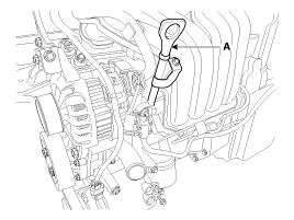
| 4. |
Remove the oil level gauge (A).
|
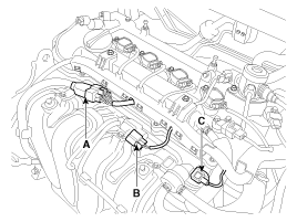
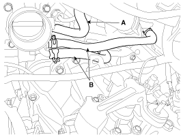
| 5. |
Disconnect the injector extension connector (A),
the VIS (Variable intake system) connector (B) and the PCSV (Purge control
solenoid valve) connector (C).
|
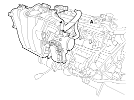
| 6. |
Disconnect the ETC (Electronic throttle control)
connector (A) and the MAPS (Manifold absolute pressure sensor) & IATS
(Intake air temperature sensor) connector (B).
|

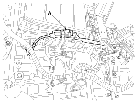
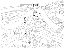
| 7. |
Disconnect the knock sensor connector (A) and remove
it from the bracket.
|
| 8. |
Disconnect the PCV (Positive crankcase ventilation)
hose (A) and the PCSV (Purge control solenoid valve) hose (B).
|
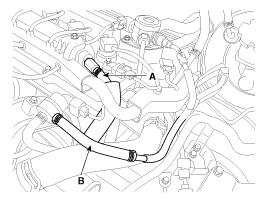
| 9. |
Disconnect the vacuum hose (A) and the throttle body
coolant hoses (B).
|
| 10. |
Unfasten the filler neck assembly mounting bolts
(A).
|
| 11. |
Remove the intake manifold (A) with the gasket (B).
|
| 12. |
Installation is reverse order of removal.
|
 Intake Manifold. Components
and Components Location
Intake Manifold. Components
and Components Location
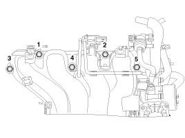
Components
1. Intake manifold
2. Intake manifold gasket
3. Electronic throttle body gasket
4. Electronic throttle body
5. Bracket
...
 Exhaust Manifold. Components
and Components Location
Exhaust Manifold. Components
and Components Location
Components
1. Heat protector
2. Exhaust manifold
4. Exhaust manifold gasket
5. Exhaust manifold stay
...
See also:
Lubricants
Items
Specified lubricants
Quantity
Input shaft spline
CASMOLY L9508
0.2g
clutch release cylind ...
Installation
1.
Installation is the reverse of removal.
•
...
General
1.
Basically, all measurements in this manual are taken with a tracking
gauge.
2.
When a measuring tape is used, check to be sure there is ...
Hyundai Accent Manuals

© 2011-2026 Copyright www.hamanual.com