 Hyundai Accent: Replacement
| 1. |
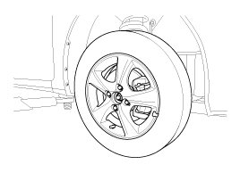
Remove the front wheel & tire.
|
| 2. |
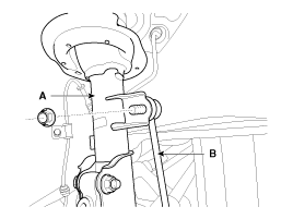
Disconnect the stabilizer link with the front strut assembly after
loosening the nut.
|
| 3. |
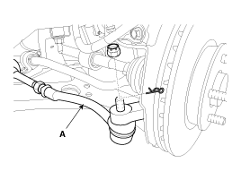
Loosen the nut and then remove the tie-rod end (A) with the front
axle.
|
| 4. |
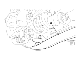
Loosen the nut and then remove the lower arm (A).
|
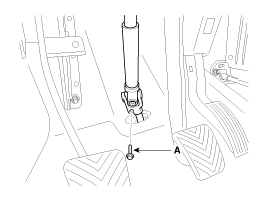
| 5. |
Loosen the bolt (A) and then disconnect the universal joint assembly
from the pinion of the steering gear box.
|
| 6. |
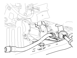
Remove the rubber hanger (A).
|
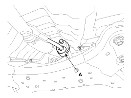
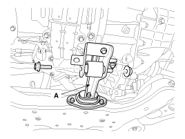
| 7. |
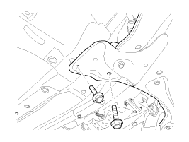
Remove the cross member from the body by loosening the roll rod
(A) mounting bolts and nuts.
|
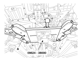
| 8. |
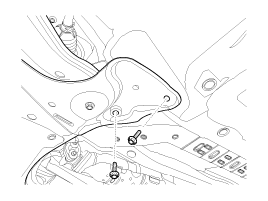
Loosen the bolts & nuts and then remove the front sub frame (A).
|
| 9. |
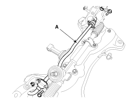
Remove the stabilizer (A) from the front sub frame by loosening
the mounting bolts & nuts.
|
| 10. |
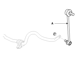
Disconnect the stabilizer link (A) with the stabilizer bar by
loosening the nut.
|
| 11. |
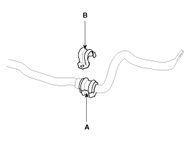
Remove the bushing (A) and the clamp (B) from the stabilizer bar.
|
| 12. |
Installation is the reverse of removal.
|
 Inspection
1.
Check the bushing for wear and deterioration.
2.
Check the front stabilizer bar for deformation.
3.
Check th ...
See also:
Removal
1.
Disconnect the battery negative cable, and wait for at least three
minutes before beginning work.
2.
Remove the lower anchor bolt.
...
Key operations
Used to start the engine, lock and unlock the doors.
WARNING - Ignition key
Leaving children unattended in a vehicle with the ignition key is dangerous
even if the key is not in the ignition swit ...
Wheel nut tightening torque
Steel wheel & aluminum alloy wheel:
65~79 lb·ft (9~11 kg·m)
If you have a tire gauge, remove the valve cap and check the air pressure. If
the pressure is lower than recommended, drive slowly ...
Hyundai Accent Manuals
© 2011-2026 Copyright www.hamanual.com

