 Hyundai Accent: Removal
| 1. |
Release the residual pressure in fuel line (Refer
to “Release Residual Pressure in Fuel Line” in this group).
|
| 2. |
Remove the rear seat [LH] (Refer to “Seat” in BD
group).
|
| 3. |
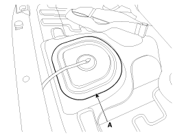
Remove the fuel pump service cover (A).
|
| 4. |
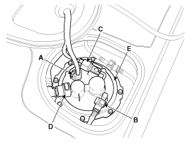
Disconnect the fuel pump connector (A).
|
| 5. |
Disconnect the fuel feed tube quick connector (B).
|
| 6. |
Disconnect the fuel tank pressure sensor connector
(C).
|
| 7. |
Disconnect the vapor tube quick-connector (D).
|
| 8. |
Remove the plate cover (E) after removing the installation
bolts, and then remove the fuel pump from the fuel tank.
|
 Installation
1.
Installation is reverse of removal.
Fuel pump plate
cover installation bolt :
1.96 ~ 2.94 N.m (0.2 ~ 0.3 kgf.m, 1.44 ~
2 ...
See also:
Pre-tensioner seat belt
Your vehicle is equipped with driver's and front passenger's pre-tensioner seat
belts. The purpose of the pre-tensioner is to make sure that the seat belts fit
tightly against the occupa ...
Installation
•
Install the component with the specified
torques.
•
...
Description and Operation
Warning Lamp Activation
Warning Lamp Behavior after Ignition
On
As soon as the operating voltage is applied to the SRSCM ignition input,
the SRSCM activates the warning lamp fo ...
Hyundai Accent Manuals
© 2011-2026 Copyright www.hamanual.com


