 Hyundai Accent: Installation
|
| 1. |
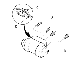
Apply sealant (C) between the wheel cylinder (B) and backing plate
(D), and install the wheel cylinder.
|
| 2. |
Connect the brake tubes (A) to the wheel cylinder.
|
| 3. |
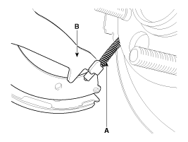
Connect the parking brake cable (A) to the brake shoe.
|
| 4. |
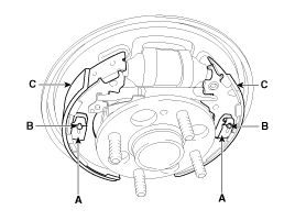
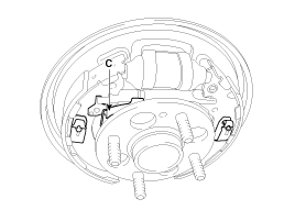
Install the brake shoes (C) onto the backing plate. Be careful
not to damage the wheel cylinder dust covers.
|
| 5. |
Install the shoe hole down pins (B) and the shoe hole down springs
(A).
|
| 6. |
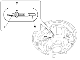
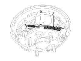
Clean the threaded portions of adjuster sleeve (A) and push rod
female (B). Coat the threads of the adjuster assembly with grease. To
shorten the clevises, turn the adjuster bolt (C).
|
| 7. |
Hook the shoe adjuster lever (C), then install it to the brake
shoe.
|
| 8. |
Install the adjuster assembly (B) and upper return spring (A)
as right direction. Be careful not to damage the wheel cylinder dust
covers.
|
| 9. |
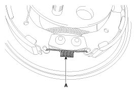
Install the lower return spring (B).
|
| 10. |
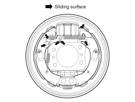
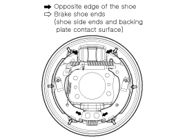
Apply brake cylinder grease or equivalent rubber grease to the
sliding surfaces shown. Don't get grease on the brake linings.
|
| 11. |
Apply brake cylinder grease or equivalent rubber grease to the
brake shoe ends and opposite edges of the shoes shown. Don't get grease
on the brake linings.
|
| 12. |
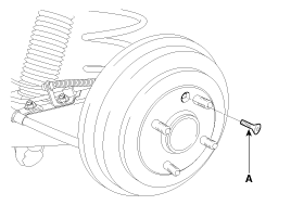
Install the rear brake drum (A).
|
| 13. |
If the wheel cylinder has been removed, bleed the brake system.
|
| 14. |
Depress the brake pedal several times to set the self-adjusting
brake.
|
| 15. |
Adjust the parking brake.
|
 Removal
•
Frequent inhalation of brake pad dust, regardless of material
composition, could be hazardo ...
 Inspection
•
Frequent inhalation of brake pad dust, regardless of material
composition, could be hazardo ...
See also:
Tire specification and pressure label
The tires supplied on your new vehicle are chosen to provide the best performance
for normal driving.
The tire label located on the driver's side center pillar gives the tire pressures
reco ...
Closing the fuel filler lid
1. To install the cap, turn it clockwise until it “click” one time. This indicates
that the cap is securely tightened.
2. Close the fuel filler lid and push it in lightly making sure that it is ...
ECM Terminal And Input/Output signal [A/T]
ECM Terminal Function
(A/T)
Connector [EGGA-AG]
Pin No.
Description
Connected to
1
Injector (Cylinder #1) [High] ...
Hyundai Accent Manuals
- Hyundai Accent 2017-2022 Service Manual
- Hyundai Accent 2010-2025 Owners Manual
- Hyundai Accent 2010-2025 Service Manual
© 2011-2025 Copyright www.hamanual.com

