 Hyundai Accent: Inspection
Hyundai Accent RB (2010-2018) Service Manual / Body Electrical System / Horn / Repair procedures / Inspection
Horn Inspection
Test the horn by connecting battery voltage to the 2 terminal and ground
the 1 terminal.

1 : 12V Ground(-)
2 : 12V (+)
Take care not to damage the horn when connecting the battery voltage
to the correct terminal.
|
The horn should make a sound. If the horn fails to make a sound, replace
it.
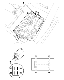
Horn Relay Inspection
| 1. |
Remove the horn relay (A) from the engine room relay box.
|
| 2. |
There should be continuity between the No.30 and No.87 terminals
when power and ground are connected to the No.85 and No.86 terminals.
|
| 3. |
There should be no continuity between the No.30 and No.87 terminals
when power is disconnected.
|
 Removal
1.
Remove the mounting bolt and disconnect the horn connector, then
remove the horn (A).
...
See also:
Removal
When replacing the ECM, the vehicle equipped with
the immobilizer must be performed procedure as below.
[In the ...
Fuse/relay panel description
Inside the fuse/relay panel covers, you can find the fuse/relay label describing
fuse/relay name and capacity.
NOTICE
Not all fuse panel descriptions in this manual may be applicable to your ve ...
Heating and air conditioning
1. Start the engine.
2. Set the mode to the desired position.
For improving the effectiveness of heating and cooling;
- Heating:
- Cooling:
3. Set the temperature control to the desired positio ...
Hyundai Accent Manuals
В© 2011-2026 Copyright www.hamanual.com


