 Hyundai Accent: Replacement
| 1. |
Loosen the wheel nuts slightly.
Raise the vehicle, and make sure it is securely supported.
|
| 2. |
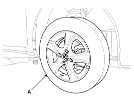
Remove the front wheel and tire (A) from front hub.
|
| 3. |
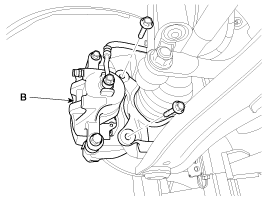
Remove the brake caliper mounting bolts, and then place the brake
caliper assembly (B) with wire.
|
| 4. |
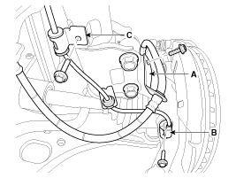
Remove the brake hose mounting bracket (A) & wheel speed sensor
(B) & bracket (C).
|
| 5. |
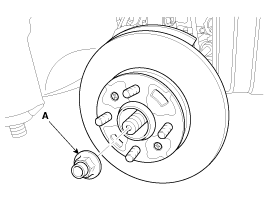
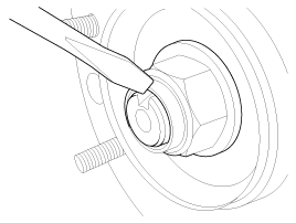
Remove driveshaft nut (A) from the front hub under applying the
brake.
|
| 6. |
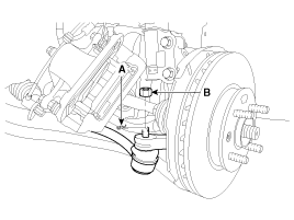
Remove the tie rod end ball joint from the knuckle.
|
| 7. |
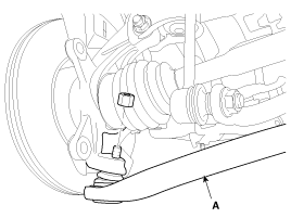
Remove the lower arm (A) from the knuckle.
|
| 8. |
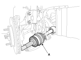
Disconnect the driveshaft (A) from the front hub assembly.
|
| 9. |
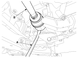
Insert a pry bar (A) between the transaxle case and joint case,
and separate the drive shaft (B) from the transaxle case.
|
| 10. |
Install in the reverse order of removal.
|
 Inspection
1.
Check the driveshaft boots for damage and deterioration.
2.
Check the driveshaft spline for wear or damage.
3.
...
See also:
Transmitter precautions
NOTICE
The transmitter will not work if any of following occur:
The ignition key is in ignition switch.
You exceed the operating distance limit (about 90 feet [30 m]).
The battery in the tra ...
Front fog light
Fog lights are used to provide improved visibility when visibility is poor due
to fog, rain or snow etc. The fog lights will turn on when fog light switch (1)
is turned to ON after the headlight ...
Components and Components Location
Component Location
1. -
2. Start relay
3. Cooling fan relay(High)
4. -
5. Main relay
6. Horn relay
7. Air conditioner relay
8. Cooling fan relay(Low)
...
Hyundai Accent Manuals
© 2011-2026 Copyright www.hamanual.com

