 Hyundai Accent: Replacement
| 1. |
Remove the front wheel & tire.
|
| 2. |
Disconnect the stabilizer link with the front strut assembly after
loosening the nut.
|
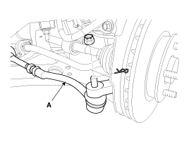
| 3. |
Loosen the nut and then remove the tie-rod end (A) with the front
axle.
|
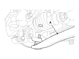
| 4. |
Loosen the nut and then remove the lower arm (A).
|
| 5. |
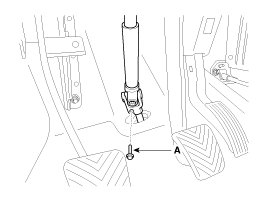
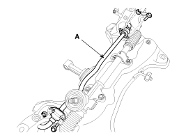
Loosen the bolt (A) and then disconnect the universal joint assembly
from the pinion of the steering gear box.
|
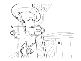
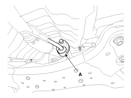
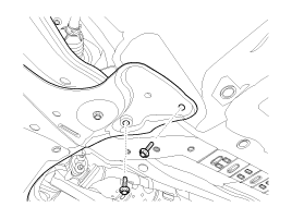
| 6. |
Remove the rubber hanger (A).
|
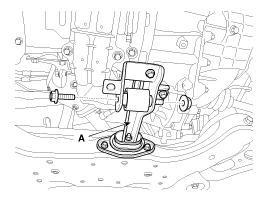
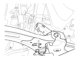
| 7. |
Remove the cross member from the body by loosening the roll rod
(A) mounting bolts and nuts.
|
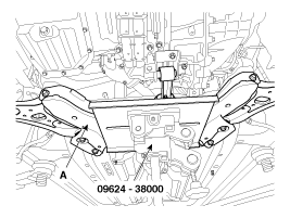
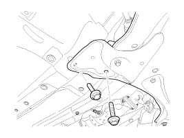
| 8. |
Loosen the bolts & nuts and then remove the front sub frame (A).
|
| 9. |
Remove the stabilizer (A) from the front sub frame by loosening
the mounting bolts & nuts.
|
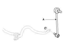
| 10. |
Disconnect the stabilizer link (A) with the stabilizer bar by
loosening the nut.
|
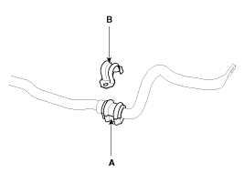
| 11. |
Remove the bushing (A) and the clamp (B) from the stabilizer bar.
|
| 12. |
Installation is the reverse of removal.
|

 Inspection
1.
Check the bushing for wear and deterioration.
2.
Check the front stabilizer bar for deformation.
3.
Check th ...
See also:
ESC OFF Switch. Repair
procedures
Inspection
1.
Turn ignition switch OFF and disconnect the negative (-) battery
cable.
2.
Remove the crash pad lower panel.
(Refer ...
Front Hub / Knuckle. Components
and Components Location
Components
1. Snap ring
2. Bearing
3. Axle assembly
4. Brake disc dust cover
5. Wheel hub assembly
6. Wheel brake disc
7. Brake disc fixing screw
8. Wh ...
Push-starting
Your manual transaxle-equipped vehicle should not be push-started because it
might damage the emission control system.
Vehicles equipped with automatic transaxle cannot be push-started. Follow the ...
Hyundai Accent Manuals

© 2011-2026 Copyright www.hamanual.com