 Hyundai Accent: Removal
| 1. |
Turn the ignition switch OFF and disconnect the battery
negative (-) cable.
|
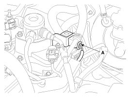
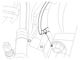
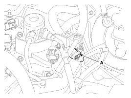
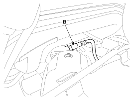
| 2. |
Disconnect the connector (A), and then remove the
sensor (B).
[Bank 1 / Sensor 1]
[Bank 1 / Sensor 2]
|
 Inspection
1.
Turn the ignition switch OFF.
2.
Disconnect the HO2S connector.
3.
Measure resistance between the HO2S termi ...
 Installation
•
Install the component with the specified
torques.
•
...
See also:
General Service Information
Protection Of The Vehicle
Always be sure to cover fenders, seats, and floor areas before
starting work.
The support rod m ...
Center console storage
To open the center console storage, pull up the lever. ...
Lighting control
The light switch has a Headlight and a Parking light position.
To operate the lights, turn the knob at the end of the control lever to one of
the following positions:
(1) OFF position
(2) Parki ...
Hyundai Accent Manuals

© 2011-2026 Copyright www.hamanual.com