 Hyundai Accent: Fuel Filter. Repair procedures
Hyundai Accent RB (2010-2018) Service Manual / Engine Control/Fuel System / Fuel Delivery System / Fuel Filter. Repair procedures
Replacement
| 1. |
Remove the fuel pump (Refer to “Fuel Pump” in this
group).
|
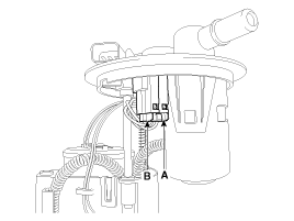
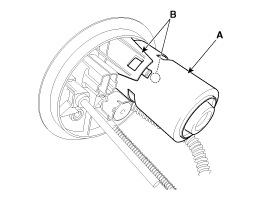
| 2. |
Disconnect the electric pump wiring connector (A)
and the fuel sender connector (B).
|
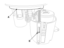
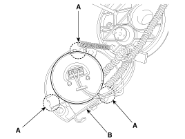
| 3. |
Remove the head assembly (A) after releasing the
cushion fixing clip (B).
|
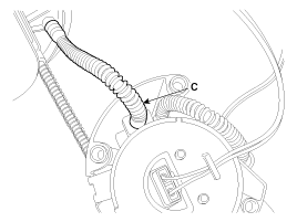
| 4. |
Disconnect the fuel tube quick-connectors (C).
|
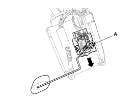
| 5. |
Remove the fuel sender (A) in the direction of an
arrow.
|
| 6. |
Disconnect the fuel tube connector (A).
|
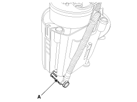
| 7. |
Remove the cut valve (A) after releasing hooks (B).
|
| 8. |
Remove the reservior-cup (B) after releasing the
fixing hooks (A).
|
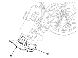
| 9. |
Release the fixing hooks, and then remove the pre-filter
(A) and the fuel pressure regulator (B).
|
| 10. |
Replace new fuel filter.
1. Head Assembly
2. Electric Pump Motor
3. Fuel Filter
4. Fuel Sender
5. Fuel Pressure Regulator
6. Pre-filter
7. Reservoir cup
|

 Inspection
[Fuel pump]
1.
Turn ignition switch OFF and disconnect the negative
(-)battery cable.
2.
Remove the fuel pump assembly.
...

See also:
Removal
•
Frequent inhalation of brake pad dust, regardless of material
composition, could be hazardo ...
Tightening Torques
Item
kgf.m
N.m
lb-ft
Positive crankcase ventilation valve installation
0.8 ~ 1.2
7.8 ~ 11.8
5.8 ~ 8.7
...
Description and Operation
Description
The hydraulic system consists of oil, an oil filter, an oil pump, and
a valve body (valves and solenoid valves). The oil pump is powered by the engine.
ATF passes through the oil ...
Hyundai Accent Manuals

© 2011-2026 Copyright www.hamanual.com