 Hyundai Accent: Inspection
Hyundai Accent RB (2010-2018) Service Manual / Body Electrical System / Horn / Repair procedures / Inspection
Horn Inspection
Test the horn by connecting battery voltage to the 2 terminal and ground
the 1 terminal.

1 : 12V Ground(-)
2 : 12V (+)
Take care not to damage the horn when connecting the battery voltage
to the correct terminal.
|
The horn should make a sound. If the horn fails to make a sound, replace
it.
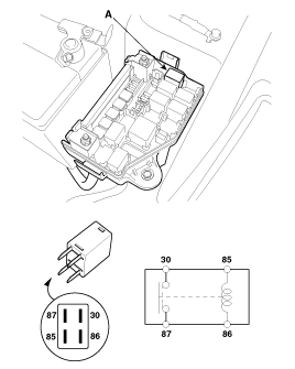
Horn Relay Inspection
| 1. |
Remove the horn relay (A) from the engine room relay box.
|
| 2. |
There should be continuity between the No.30 and No.87 terminals
when power and ground are connected to the No.85 and No.86 terminals.
|
| 3. |
There should be no continuity between the No.30 and No.87 terminals
when power is disconnected.
|
 Removal
1.
Remove the mounting bolt and disconnect the horn connector, then
remove the horn (A).
...
See also:
Installation
1.
Installation is the reverse of removal.
•
...
Steering Gear box. Components and
Components Location
Components
1. Tie-rod end
2. Lock nut
3. Bellows clip
4. Bellows
5. Tie rod
6. Rack bar
7. Dust packing
8. Dust cap
9. Oil seal
10. Pinion plug
...
Instrument panel illumination
When the vehicle’s parking lights or headlights are on, press the upper or lower
part of the switch to adjust the brightness of the instrument panel illumination. ...
Hyundai Accent Manuals
© 2011-2026 Copyright www.hamanual.com


