 Hyundai Accent: Removal
| 1. |
Turn ignition switch OFF.
|
| 2. |
Remove the battery and battery tray.
(Refer to Engine Electrical group - "Battery")
|
| 3. |
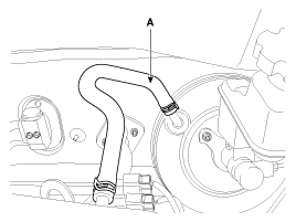
Disconnect the vacuum hose (A) from the brake booster.
|
| 4. |
Remove the master cylinder.
(Refer to Master cylinder.)
|
| 5. |
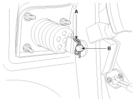
Remove the snap pin (A) and clevis pin (B).
|
| 6. |
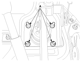
Remove the brake booster mounting nuts (A).
|
| 7. |
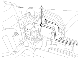
Disconnect the brake tubes (A) from the HECU by unlocking the
nuts counterclockwise with a spanner.
|
| 8. |
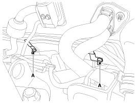
Remove the brake tubes mounting nuts (A).
|
| 9. |
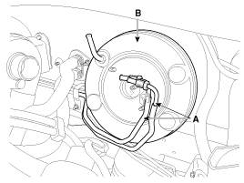
Pivot the brake tubes (A) down out of the way.
|
| 10. |
Remove the brake booster (B).
|
 Brake Booster Operating Test
For simple checking of the brake booster operation, carry out the following
tests.
1.
Run the engine for one or two minutes, and then stop it. If the
pedal depresses ...
 Inspection
1.
Inspect the check valve in the vacuum hose.
Do not remove the check valve f ...
See also:
Front Impact Sensor (FIS). Components and Components
Location
Components
...
Components and Components Location
Component Location
1. -
2. Start relay
3. Cooling fan relay(High)
4. -
5. Main relay
6. Horn relay
7. Air conditioner relay
8. Cooling fan relay(Low)
...
Removal
1.
Remove the transaxle assembly. (Refer to "Manual
transaxle system" in MT group)
2.
Remove the clutch cover bolts. Be careful ...
Hyundai Accent Manuals
В© 2011-2025 Copyright www.hamanual.com

