 Hyundai Accent: Starter Relay. Repair procedures
Hyundai Accent RB (2010-2018) Service Manual / Engine Electrical System / Starting System / Starter Relay. Repair procedures
Inspection
| 1. |
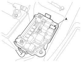
Remove the fuse box cover.
|
| 2. |
Remove the starter relay(A).
|
| 3. |
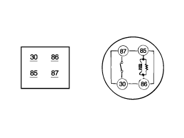
Using an ohmmeter, check that there is continuity
between each terminal.
|
| 4. |
Apply 12V to terminal 85 and ground to terminal 86.
Check for continuity between terminals 30 and 87.
|
| 5. |
If there is no continuity, replace the starter relay.
|
| 6. |
Install the starter relay.
|
| 7. |
Install the fuse box cover.
|
 Cleaning
1.
Do not immerse parts in cleaning solvent.
Immersing the yoke assembly and/or armature will
damage the insulation wipe these parts with a cloth only.
...
See also:
Engine Mounting. Components and Components Location
Components
1. Transaxle mounting bracket
2. Rear roll stopper
3. Engine mounting bracket
4. Engine mounting support bracket
...
35R Clutch Control Solenoid Valve(35R/C_VFS). Schematic Diagrams
Circuit Diagram
...
Inspection
Armature
1.
Remove the starter.
2.
Disassemble the starter as shown at the beginning
of this procedure.
3 ...
Hyundai Accent Manuals
- Hyundai Accent 2017-2022 Service Manual
- Hyundai Accent 2010-2025 Owners Manual
- Hyundai Accent 2010-2025 Service Manual
В© 2011-2025 Copyright www.hamanual.com


