 Hyundai Accent: Inspection
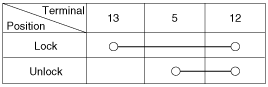
Driver Door Lock Switch Inspection
| 1. |
Disconnect the negative (-) battery terminal.
|
| 2. |
Remove the front door trim panel.
(Refer to the BD group - "Front door")
|
| 3. |
Disconnect the connector from the power window switch module.
|
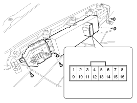
| 4. |
Check for continuity between the terminals in each switch position
according to the table.
|

 Removal
1.
Disconnect the negative(-) battery terminal.
2.
Remove the front door trim panel.
(Refer to the BD group - "Front door")
...
See also:
Removal
Passenger Compartment Junction Box
1.
Disconnect the negative(-) battery terminal.
2.
Remove the crash pad lower panel.
(Refer to t ...
Inspection
1.
Turn the ignition switch OFF.
2.
Disconnect the PCSV connector.
3.
Measure resistance between the PCSV termi ...
Description
Automatic transaxle system relies on various measurement data to determine
the current control status and extrapolate the necessary compensation values.
These values are used to control the a ...
Hyundai Accent Manuals

© 2011-2026 Copyright www.hamanual.com