 Hyundai Accent: Disassembly
| 1. |
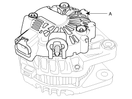
Remove the rear cover (A).
|
| 2. |
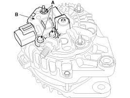
Loosen the mounting bolts(A) and disconnect the brush
holder assembly(B).
|
| 3. |
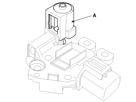
Remove the slip ring guide(A).
|
| 4. |
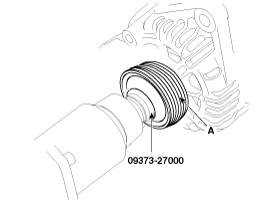
Remove the pulley(A) using the special tool.
|
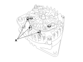
| 5. |
Unsolder the 3 stator leads(A).
|
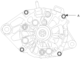
| 6. |
Loosen the 4 through bolts(A).
|
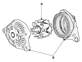
| 7. |
Disconnect the rotor(A) and bracket(B).
|
| 8. |
Reassembly is the reverse order of disassembly.
|
 Removal and Installation
1.
Disconnect the battery negative terminal first, then
the positive terminal.
Tightening torque
(-) terminal :
4.0 ~ 6. ...
 Inspection
Rotor
1.
Check that there is continuity between the slip rings
(C).
2.
Check that there is no continuity between the s ...
See also:
Replacement
1.
Remove the front wheel & tire.
Tightening torque :
88.3 ~ 107.9N.m(9.0 ~ 11.0kgf.m, 65.1 ~ 79.6lb-ft)
...
Valve Body. Description and Operation
Description
The valve body is essential to automatic transaxle control and consists
of various valves used to control the oil feed from the oil pump. Specifically,
these valves consist of pr ...
SRS components and functions
The SRS consists of the following components:
1. Driver's front air bag module
2. Passenger's front air bag module
3. Side impact air bag modules
4. Curtain air bag modules
5. Retractor ...
Hyundai Accent Manuals
- Hyundai Accent 2017-2022 Service Manual
- Hyundai Accent 2010-2025 Owners Manual
- Hyundai Accent 2010-2025 Service Manual
В© 2011-2025 Copyright www.hamanual.com

