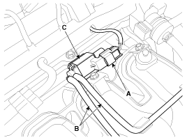
 Hyundai Accent: Removal
| 1. |
Turn the ignition switch OFF and disconnect the battery
negative (-) cable.
|
| 2. |
Disconnect the variable intake solenoid valve connector
(A).
|
| 3. |
Disconnect the vacuum hoses (B) from the valve.
|
| 4. |
Remove the installation bolt, and then remove the
valve (C) from the surge tank.
|
 Inspection
1.
Turn the ignition switch OFF.
2.
Disconnect the VIS valve connector.
3.
Measure resistance between VIS valve ...
 Installation
•
Install the component with the specified
torques.
•
...
See also:
Removal
1.
Drain the brake fluid through the bleed plug (A).
2.
Remove the clutch release cylinder assembly (C) after
removing thd tube (B) ...
Components and Components Location
Components Location
[Vehicle Components]
1. Automatic transaxle
2. Transaxle control module (TCM)
3. Shift lever
4. (DLC)
[Transaxle Components ...
Consumer information
This consumer information has been prepared in accordance with regulations issued
by the National Highway Traffic Safety Administration of the U.S. Department of
Transportation. Your Hyundai deale ...
Hyundai Accent Manuals
© 2011-2026 Copyright www.hamanual.com

